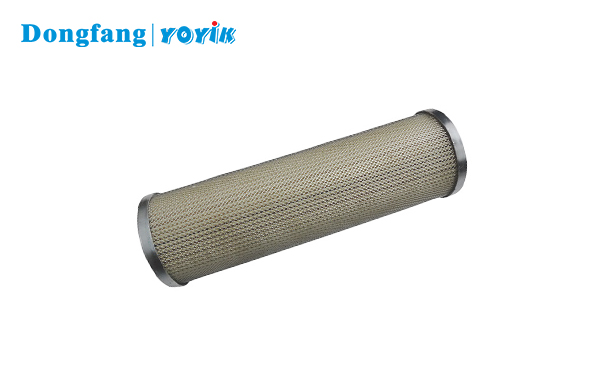
1. Product Overview
The YOYIK ZNGL02011001 is a lubricating oil station filter element built for the bearing lube circuits of induced draft fans in thermal power plants. It installs in the duplex filter housing of the lube oil station, on the pressure side of the circuit — between the pump outlet and the fan bearing housings.
Induced draft fan bearings run under continuous mechanical load and elevated temperatures. What that means in practice is that the oil feeding those bearings has to stay clean, consistently. Particulate contamination in a lube circuit doesn’t just wear bearings faster — it degrades the oil itself, shortens drain intervals, and increases the chance of an unplanned trip. The ZNGL02011001 handles filtration at the oil station level, catching debris before it circulates.
YOYIK manufactures this element to fit the standard induced draft fan lube oil station housings commonly used across Chinese power generation units. It is a direct replacement for systems specified to ZNGL02011001 — no housing modification needed.
2. Performance Features
- Filtration efficiency: Rated at β₁₀ ≥ 200 per ISO 16889 — particles 10 microns and above are captured reliably, keeping oil cleanliness within the range that bearing lube circuits require.
- Collapse resistance: The element core handles differential pressures well above the bypass valve set point, so it holds its shape during cold starts when oil viscosity is high and flow resistance spikes briefly.
- Fluid compatibility: Media and seal materials work with both conventional mineral turbine oil and fire-resistant fluids, covering the range of fluids used in induced draft fan auxiliary systems.
- Low clean differential pressure: Pleated media packs more filtration area into a shorter element, keeping initial flow resistance low and pushing the bypass threshold further out in service life.
- Stable media construction: Inner and outer perforated steel cores hold the media pack in place through flow surges — during startup, pump switchover, or any event that temporarily spikes flow rate.
- End-cap sealing: End caps are bonded to the media pack. FKM O-rings at the upper end cap seat against the housing port and prevent unfiltered oil from reaching the clean side without passing through the media.
- Drop-in compatibility: Dimensions match standard ZNGL02011001 housings, which simplifies spares ordering and means maintenance teams don’t have to verify fit unit by unit.
3. Working Principle
Oil from the lube oil station pump enters the filter housing under pressure and flows from the outside of the element inward through the pleated glass fiber media. Contaminants accumulate on the outer surface of the media pack. The filtered oil passes through the inner perforated steel core and exits through the center outlet tube into the bearing lube circuit downstream.
Over time, as the media captures more particulate, the differential pressure across the element climbs. Most induced draft fan lube oil station configurations set the bypass valve at 0.35 MPa. When differential pressure hits that point, the bypass valve opens to keep oil flowing to the bearings — but at that stage, the element has reached the end of its useful life and needs to be swapped out.
The duplex filter housing design lets one chamber be isolated and serviced while the other stays in service. Element replacement doesn’t require an oil supply interruption, which matters for base-load units where bearing oil cannot be stopped mid-operation.
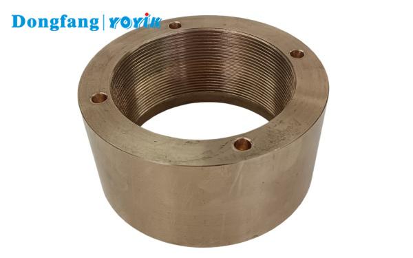
4. Product Structure
The ZNGL02011001 element is made up of six main components:
- Outer perforated steel core: Guards the media pack against physical damage during handling and installation, and prevents inward collapse under normal operating differential pressure.
- Filter media pack: Multi-layer pleated glass fiber with a controlled pore structure. The pleating substantially increases the active filtration area relative to the element’s physical size, which supports both flow capacity and the volume of contamination the element can hold before differential pressure rises.
- Inner perforated steel core: Supports the media from inside — particularly during backpressure events at startup — and channels clean oil toward the outlet.
- Upper end cap: Rigid hard plastic construction, carrying the FKM O-ring that seals against the housing outlet port. If this seal fails or is damaged during installation, unfiltered oil can reach the bearing circuit without triggering any differential pressure alarm.
- Lower end cap: Hard plastic closed cap that seals the bottom of the element. All oil entering the housing must pass through the glass fiber media — there is no outlet at the lower end.
- O-ring seals: FKM (fluorocarbon) material, compatible with mineral lube oils across the temperature range typical of induced draft fan bearing systems.
| Parameter | Details |
|---|---|
| Part Number | ZNGL02011001 |
| Brand | YOYIK |
| Application | Induced draft fan lube oil station |
| Filter Type | High-pressure duplex housing element |
| Flow Direction | Outside-in |
| Media Material | Pleated glass fiber |
| Seal Material | FKM (fluorocarbon) |
| End Cap | Hard plastic |
| Compatible Fluid | Mineral turbine lube oil (L-TSA 46) |
5. Common Faults and Troubleshooting
| Fault | Likely Cause | What to Do |
|---|---|---|
| Differential pressure rises much faster than usual | Oil contamination is above normal levels; debris introduced during recent maintenance upstream | Pull an oil sample and check cleanliness class. Trace and fix the upstream contamination source. Replace the element and run offline filtration until the cleanliness class recovers. |
| Differential pressure stays low but oil cleanliness is getting worse | Internal bypass — likely a damaged end-cap O-ring or the element not seated properly in the housing | Isolate the chamber and pull the element. Inspect the O-ring and seating surface. Install a new element with fresh seals. Pressure-test the housing before putting it back in service. |
| Oil leaking from the filter housing cover | Cover gasket damaged or over-torqued; cover O-ring reused from the previous service | Isolate the chamber and bleed down pressure before opening. Replace both the gasket and O-ring. Torque the cover to the rated specification — not by feel. |
| Bypass valve opens right after a new element is installed | Standby chamber was not pre-filled before switchover; air locked in the housing | Always fill the standby chamber through the vent plug and confirm all air is out before rotating the changeover valve. Don’t switch chambers with an air-bound housing. |
| Element found collapsed or distorted during inspection | Element run well past its service life; bypass valve did not open when it should have; excessive flow surge on cold start | Replace with a new ZNGL02011001 element. Test the bypass valve set point. If cold-start surges are a recurring issue, consider a staged pump start sequence to reduce peak flow rate. |
| Bearing oil temperature rises after an element change | Wrong element installed — higher flow restriction than the ZNGL02011001 spec; debris partially blocking the outlet port | Confirm the element part number before assuming the housing is the problem. Check and clear the housing outlet port. Measure actual oil flow rate against the design value for the fan. |
6. Maintenance and Inspection Guidelines
Replacement Interval
Replace the ZNGL02011001 element when differential pressure across the housing reaches 0.25–0.30 MPa — that’s the pre-alarm range for most systems, before the bypass valve opens at 0.35 MPa. That said, differential pressure alone shouldn’t dictate the replacement schedule. The element should come out at every planned major overhaul of the induced draft fan regardless of readings, or after a maximum of 4,000–8,000 operating hours, depending on how clean the oil has been kept.
Before Starting the Change-Out
- Confirm the standby filter chamber is in good condition and ready to take load before isolating the active one.
- Check the replacement element’s part number and seal material against the housing spec — a dimensionally close but incorrect element can create an internal bypass that won’t show up on any indicator.
- Inspect the element packaging. If the seal is broken or the packaging looks like it’s been opened and resealed, set it aside and use a different one.
During the Element Change
Wipe down the area around the filter housing cover before breaking any connection. Use lint-free cloths — fiber from ordinary shop rags is a real contamination risk in a bearing lube circuit. Stage the new element and replacement O-rings within arm’s reach before opening the housing, so the port isn’t left exposed any longer than necessary.
When pulling the old element, drain any residual oil into a clean container rather than letting it run down the housing exterior. Check inside the housing for sludge or deposit buildup. If you find any, flush with clean filtered oil before the new element goes in.
Seals and O-Rings
Every O-ring and gasket in the housing gets replaced at each element change — no exceptions. Seals that have been under load for thousands of hours won’t re-seal reliably, and reusing them is one of the more predictable causes of post-maintenance leaks. Use a small amount of clean lube oil on new O-rings before seating them. Petroleum grease and mineral-based compounds are not compatible with the system fluid and will contaminate the circuit.
After Installation
Once the new element is in and the cover is torqued, pre-fill the chamber through the vent plug and bleed air before switching oil flow. Bring the system to operating pressure and walk the housing for external leaks before leaving it unattended. Log the replacement date and the starting differential pressure reading — trending that data over multiple intervals is the most reliable way to catch changes in system contamination levels early.