The YOYIK RZQW-03A speed and overspeed trip monitor is designed for steam turbine emergency governor systems. It detects the moment when the overspeed bolt (fly-weight) extends and retracts, records the action speeds, and provides alarm outputs. The device uses a microcontroller with anti-interference design and stores trip speeds, reset speeds, and maximum speed in non-volatile memory.
Technical Specifications
| Parameter | Value |
|---|---|
| Speed measurement range | 0000 – 9999 RPM |
| Speed accuracy | ±1 RPM |
| Alarm setpoints (default) | Overspeed 1: 3300 RPM, Overspeed 2: 3420 RPM (both NO contacts) |
| Contact output rating | DC30V/7A, AC250V/7A, AC125V/12A |
| Power supply | AC220V ±10%, 50–60Hz, power consumption <10W |
| Display | 4-digit LED |
| Analog output | 4-20mA or 0-10V (for recorder, DCS, etc.) |
Key Features & Benefits
- Records trip & reset speeds – Stores extension speed and retraction speed of each overspeed bolt (two channels).
- Peak speed memory – Memorizes the maximum speed during operation.
- Fast display mode – Shows dynamic speed 8 times per second for quick observation.
- Anti-interference design – MCU with self-reset system ensures reliable operation in turbine environments.
- Multiple outputs – Two independent overspeed alarm relays + analog signal for DCS/recorder.
- Clear front panel indicators – LED lights for overspeed 1, overspeed 2, and trip events.
- Simple operation – Dedicated keys for reset, fast display, trip speed recall, and peak speed recall.
Installation & Wiring
- Cut a 152×78 mm rectangular hole in the instrument panel.
- Insert the monitor into the hole and secure it using the two side brackets.
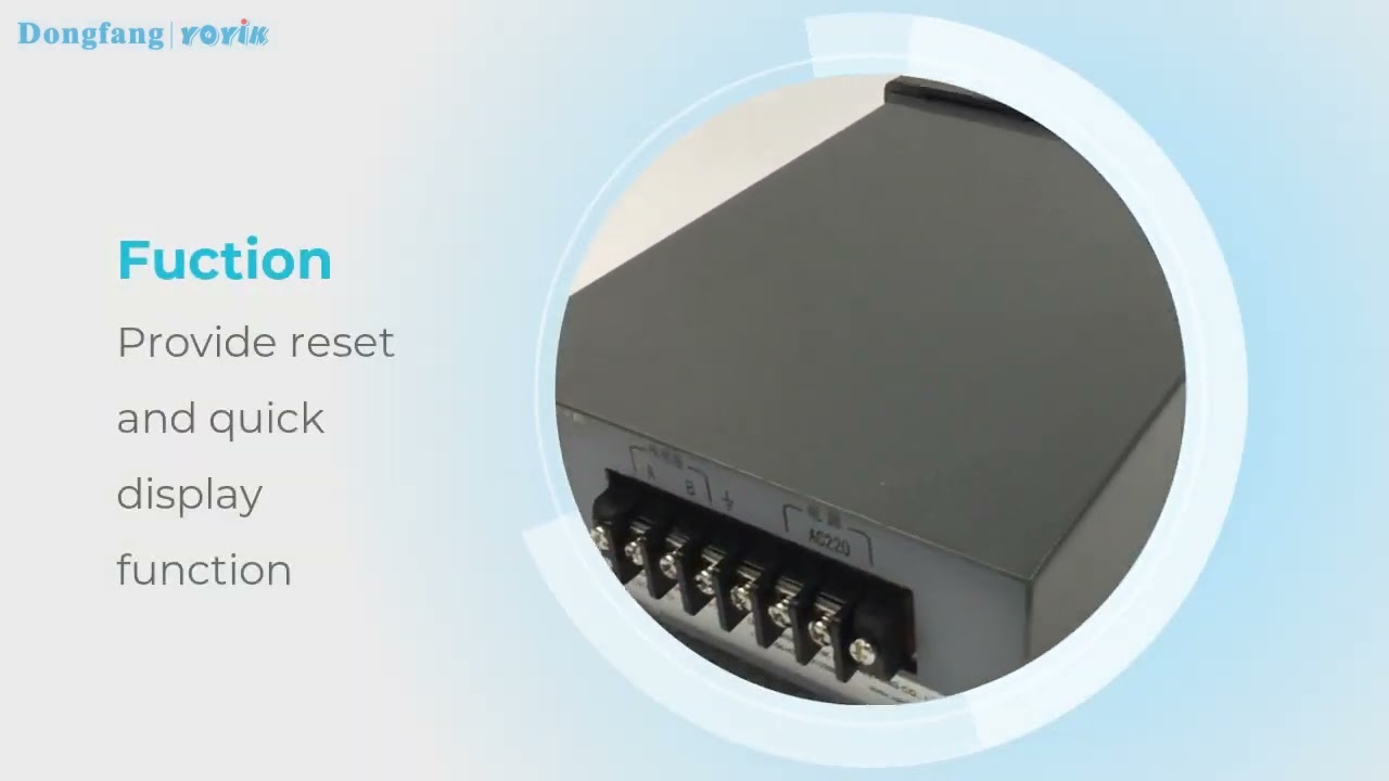
- Connect the speed sensor to the signal input terminals on the rear panel.
- Connect AC220V power supply (L/N) to the designated terminals.
- Wire alarm relay outputs (normally open contacts) to PLC, DCS, or alarm devices as needed.
- Connect analog output (4-20mA or 0-10V) to recorder or DCS if required.
- Ensure proper grounding and separate sensor/signal cables from high-voltage AC lines.
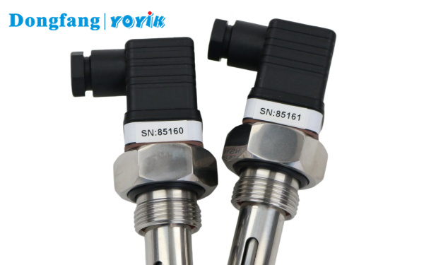
Sensor compatibility: CS-1, CS-2, CS-3 series – thread size and cable length can be customized.
Usage Precautions
- Do not exceed the rated power supply voltage (AC220V ±10%).
- Keep sensor gap to gear tooth ≤2mm (typically 0.5–1.5mm recommended).
- Route sensor cables separately from power cables to avoid electromagnetic interference.
- The trip capture function is locked out when speed is below 2000 RPM (or sensor frequency <43Hz) – this is normal.
- After a trip event or alarm, use the “Reset” key to clear latched data before restart.
- Do not open the housing – internal fuse replacement requires return to factory.
Troubleshooting & Common Faults
| Fault | Possible Cause | Remedy |
|---|---|---|
| No output signal | Power supply failure; sensor not connected; sensor gap too large; wiring loose; sensor defective | Check AC220V input; verify sensor connection to signal terminals; adjust gap to <2mm; tighten terminals; measure sensor resistance (250Ω for low impedance, 500Ω for high impedance) |
| Unstable speed reading | Sensor loose; poor contact; EMI from nearby equipment; cables routed with high-voltage lines | Fix sensor firmly; check terminal connections; remove interference sources; separate signal cables from power cables |
| No display (blank) | AC power missing; internal fuse blown | Verify 220VAC at terminals; if fuse blown, return unit to YOYIK for repair |
| Monitor does not capture trip speed | Speed below lockout threshold; sensor not detecting fly-weight; incorrect sensor type | Ensure speed >2000 RPM for trip detection; check sensor alignment with overspeed bolt; use recommended CS series sensor |