I. Product Overview
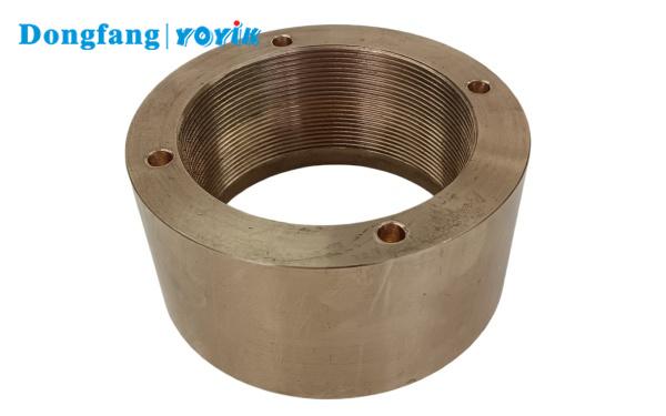
The FA1D56-01-12A is a specialized free-end impeller lock nut designed for the FA1D56 series boiler feed booster pumps. Serving as a core positioning and fastening component of the pump rotor, it is installed on the outer side of the impeller hub at the non-driven (free) end of the pump shaft and is paired with a tab lock washer. Its primary functions are to axially lock the double-suction impeller, restrict axial float, and counteract residual axial thrust generated during startup, shutdown, and variable load conditions. This ensures that the impeller remains precisely centered within the pump casing flow channels, prevents rubbing between the impeller wear rings and sealing rings, and guarantees the dynamic balance and long-term stable operation of the booster pump rotor.
This component is tailor-made for the FA1D56 horizontal, single-stage, double-suction booster pumps utilized in thermal power 300/600MW units. Widely applied in power station boiler feed water systems, it serves as a standard, interchangeable replacement part for booster pump overhauls and spare parts replacement.
II. Basic Matching Parameters
| Parameter Item | Technical Specification | Description |
| Product Model | FA1D56-01-12A | Original equipment manufacturer (OEM) part number, used for procurement, spare parts verification, and equipment maintenance ledger matching. |
| Compatible Equipment | FA1D56 Boiler Feed Booster Pump | Horizontal, axially split, single-stage, double-suction booster pump; acts as the booster pump paired with the power plant’s turbine-driven feed pump. |
| Installation Position | Outer side of the impeller at the free end (non-driven end) of the rotor | Paired with the driven-end impeller nut to achieve axial positioning and locking of the single-side impeller. |
| Applicable Medium | High-temperature boiler feed water | Operating medium temperature $\le 166^\circ\text{C}$; medium operating pressure: 0.96–1.87 MPa. |
| Rated Speed | 1480 r/min | Adapts to the standard operational speed of the FA1D56 booster pump. |
| Matching Accessory | Specialized tab lock washer | Must be installed during assembly to prevent the nut from loosening and causing rotor axial float failures due to operational vibration. |
III. Material and Processing Technology
-
Base Material: 40Cr alloy structural steel (forging), treated with overall quenching and tempering (Q&T) heat treatment, followed by a surface blackening anti-rust process. It features high tensile strength, excellent fatigue resistance, and high-temperature creep resistance, ensuring it resists deformation and thread stripping under long-term axial impact loads.
-
Thread Machining: Precision-turned trapezoidal or standard transmission threads with a 6H thread tolerance. It fits tightly with the external threads of the pump shaft, providing sufficient engagement length to completely eliminate thread damage caused by long-term fluid flushing and vibration.
-
Structural Design: Features a hexagonal locking structure compatible with standard socket wrenches for easy installation and removal. The end face is machined with anti-loosening positioning slots that interlock with the tabs of the lock washer to prevent operational loosening. The flat end face is precision-finished to ensure zero-clearance, flush contact with the impeller hub, resulting in uniform force distribution.
-
Flaw Detection: The finished product undergoes Magnetic Particle Testing (MT) non-destructive inspection to ensure it is free of cracks, blowholes, or machining defects, meeting the safety standards for high-pressure, high-temperature conditions in power station rotating equipment.
IV. Core Product Performance & Features
-
Reliable Axial Locking to Prevent Axial Float: Specifically designed to withstand alternating axial forces generated by booster pump startups, shutdowns, and flow fluctuations. It firmly locks the impeller’s axial position, eliminating common equipment failures such as impeller offset, sealing ring friction, mechanical seal damage, and excessive shaft vibration, thereby reducing the risk of unscheduled shutdowns.
-
High Strength & Fatigue Resistance for Extended Service Life: Utilizing a forged and tempered 40Cr substrate, it withstands high-speed cyclic vibrations and thermal expansion shocks from high-temperature media. The threads resist stripping, and the nut body resists cracking, making it perfectly suited for continuous 24/7 power plant operations.
-
Precision Interchangeability for Convenient Maintenance: Machined strictly according to original factory drawing dimensions, it offers absolute universality and interchangeability with the FA1D56 booster pump shaft and impeller. No secondary machining is required on-site during overhauls, ensuring high assembly compatibility and shortening the pump group maintenance period.
-
Resistance to High-Temperature Water Erosion & Corrosion: The surface blackening anti-rust process is optimized for high-temperature deaerated feed water environments, resisting trace oxygen corrosion. It will not seize up due to rust over long-term operations, facilitating smooth disassembly during future overhauls.
-
Dual Anti-Loosening via Integrated Locking Structure: The positioning slots on the nut end face pair with the OEM tab lock washer to form a mechanical locking mechanism. This effectively counteracts the vibrational forces generated by high-speed rotor rotation, eliminating the root cause of nut loosening failures.
V. Primary Application Scenarios
-
Rotor maintenance spare parts for FA1D56 series boiler feed booster pumps in thermal power plant 300MW and 600MW units.
-
Routine maintenance and overhaul replacement for turbine-driven feed pump booster pumps in cogeneration plants and captive power plants.
-
Standardized backup vulnerable fastening accessories for water pump maintenance contractors and power station spare parts warehouses.
-
Rotor assembly compatibility for FA1D56同系列 derivative models (e.g., FA1D56A) booster pumps.
VI. Installation and Maintenance Precautions
1. Assembly Specifications
Before removal or installation, thoroughly clean the pump shaft external threads and the nut internal threads to remove scale, rust, and impurities. Torque the nut uniformly according to the specified limits in the OEM maintenance manual; excessive force is strictly prohibited to prevent thread stripping or teeth collapse. After tightening, bend the tabs of the lock washer into the nut’s positioning slots to complete the mechanical anti-loosening lock.
2. Operating Condition Restrictions
This component is strictly compatible with the free-end impeller positioning of FA1D56 pumps and must not be mixed with the driven end or used on other pump models. Do not use this component in conditions exceeding $170^\circ\text{C}$ or in strong acid/alkali corrosive media environments.
3. Overhaul Replacement Criteria
During every pump rotor overhaul, the threads must be inspected for wear, collapsed teeth, and cracks. If thread stripping, nut body deformation, severe end-face wear, or micro-cracks during magnetic particle testing are detected, the entire set (Nut + Tab Lock Washer) must be replaced immediately. Repairing and reusing damaged parts is strictly prohibited.
4. Storage and Preservation
Spare parts must be stored in a dry, ventilated warehouse and coated with anti-rust grease to avoid moisture and corrosion. Store them separately to prevent impacts that could damage the threads or the hexagonal locking faces.
5. Failure Warning
If the nut is not locked securely or the lock washer is missing, it will directly induce axial impeller float, severe wear ring abrasion, excessive rotor vibration, and mechanical seal leakage. In severe cases, it can lead to catastrophic impact damage between the impeller and the pump casing.
DFYLSYC-2026-06-29-A